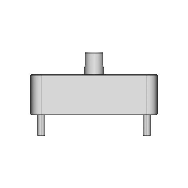
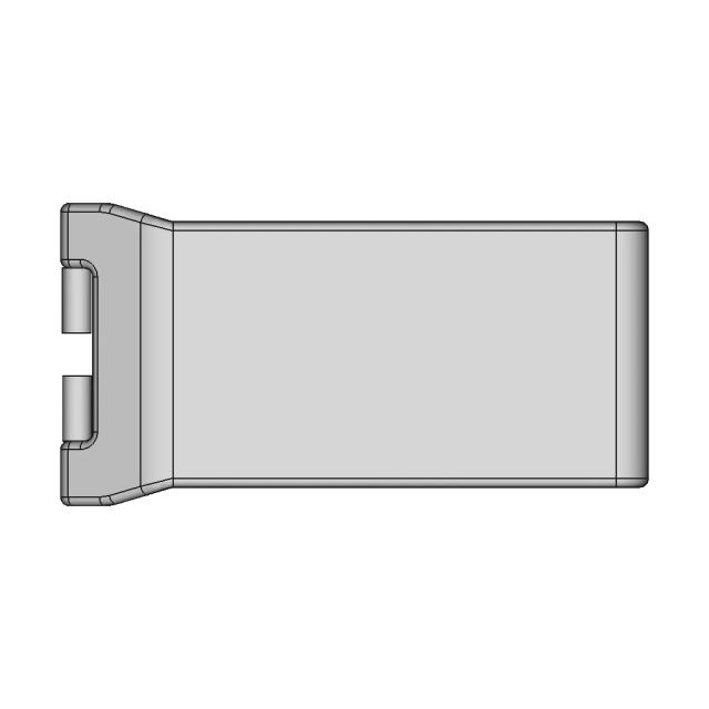
Assembly - Front View
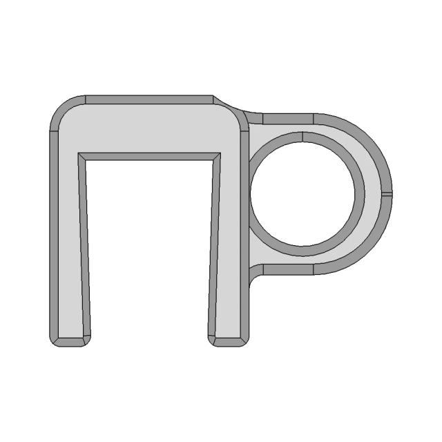
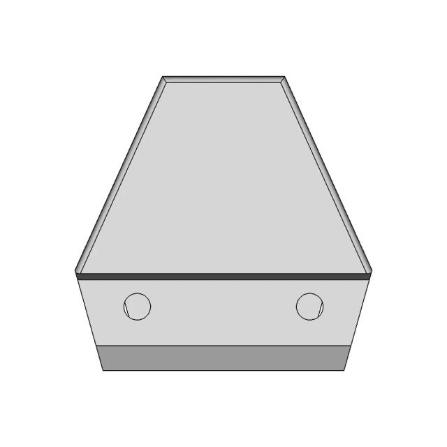
OrthographicShows overall height, mounting flange width, and central bore alignment; critical for establishing vertical envelope and shaft centerline location; reveals the two side mounting holes and top cap geometry
AI Drawing Analysis
The cards below explain how the generated drawing outputs and assets connect to the final technical sheets.
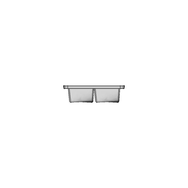
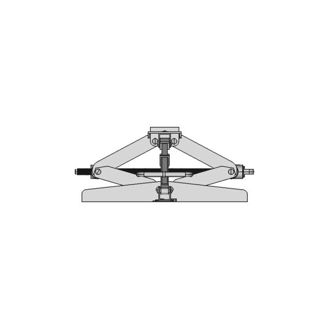
Shows overall height, mounting flange width, and central bore alignment; critical for establishing vertical envelope and shaft centerline location; reveals the two side mounting holes and top cap geometry
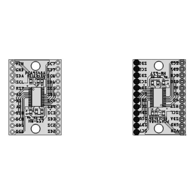
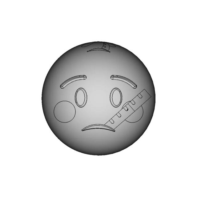
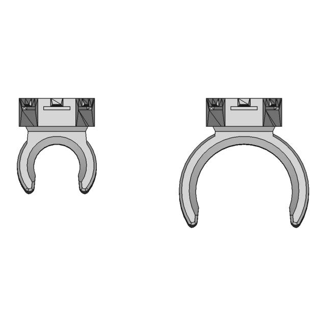
Displays the circular bore diameter, flange mounting hole pattern (2× M10), and the 123.75 mm outer diameter of the bearing housing; essential for verifying horizontal footprint and bolt hole spacing
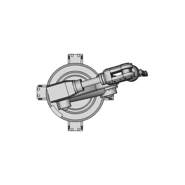
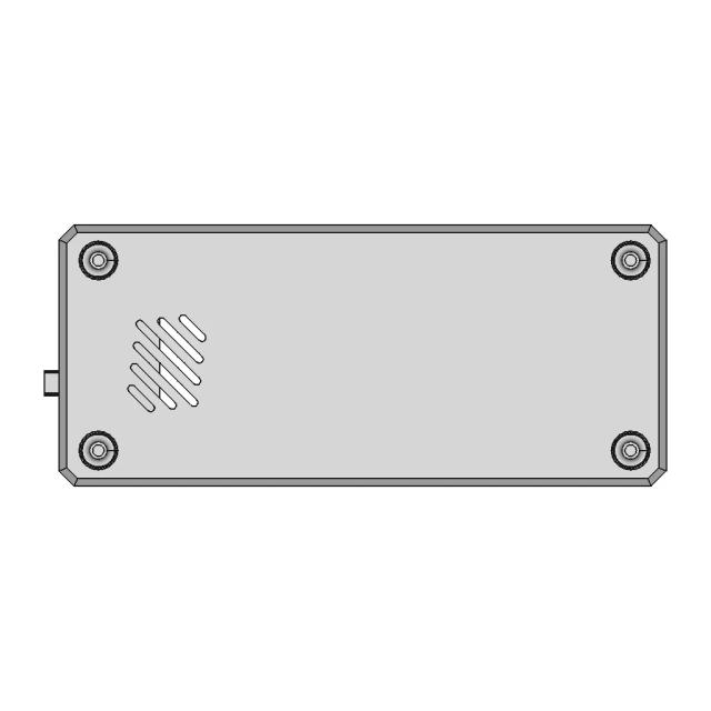
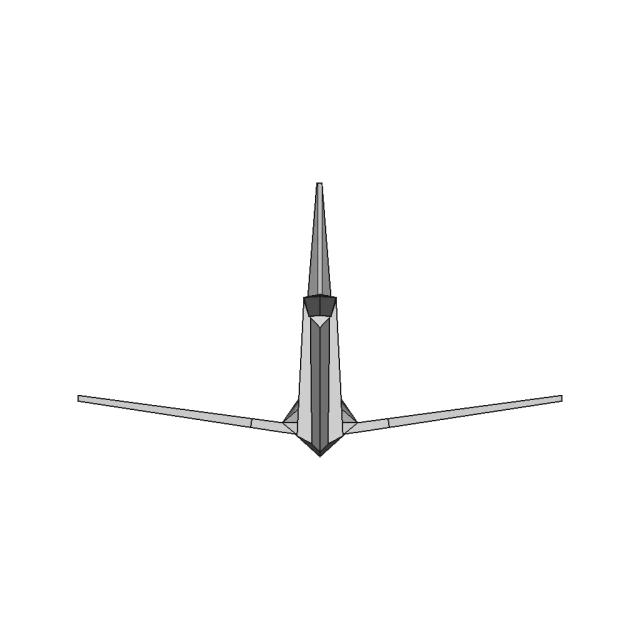
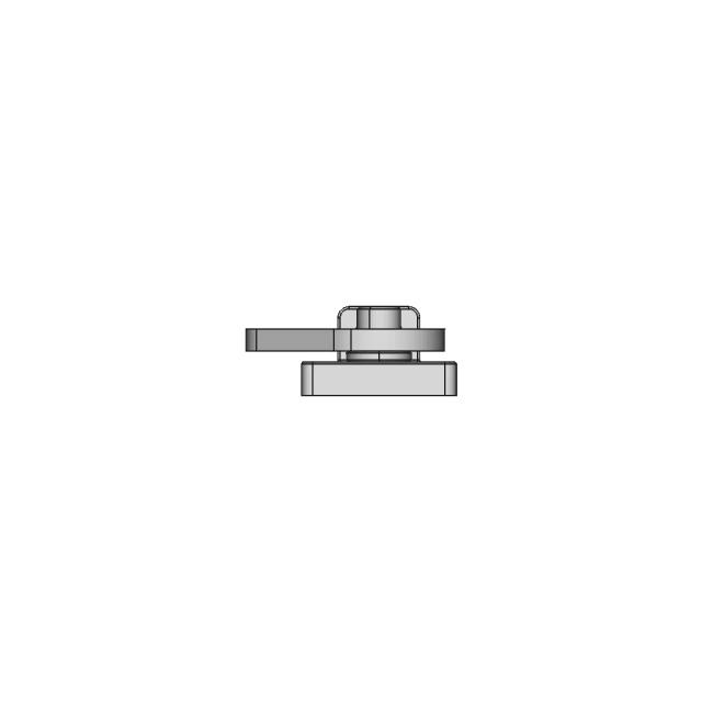
Reveals the side profile of the bearing housing, the depth of the flange, and the 60 mm inner bore wall thickness; shows the 10 mm flange thickness and the 20 mm mounting tab thickness; critical for machining and assembly sequence
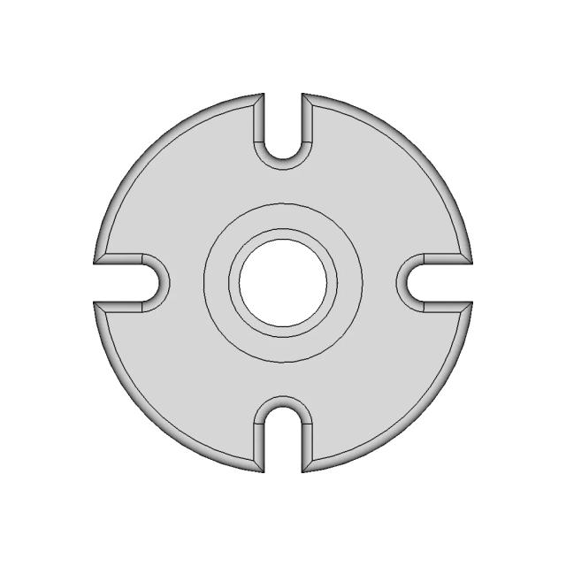
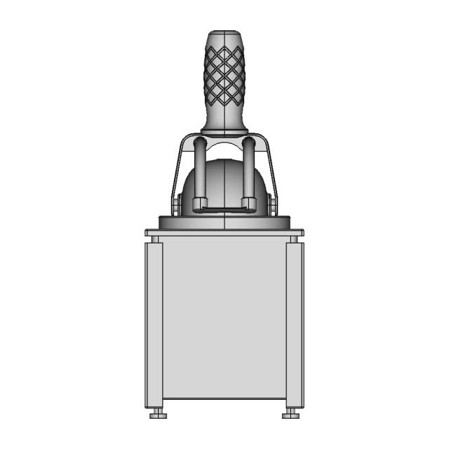
Reveals the internal bore geometry (123.75 mm ID), the 60 mm inner race bore, and the 77.7 mm intermediate bore; shows wall thicknesses and the bearing seat depth for proper fit
Reveals the internal bore geometry (123.75 mm ID), the 60 mm inner race bore, and the 77.7 mm intermediate bore; shows wall thicknesses and the bearing seat depth for proper fit
Magnifies the 10 mm M10 mounting hole pattern and the 6.15 mm set screw hole; critical for verifying thread depth, hole clearance, and interference with adjacent features
Downloads
Each sheet available in PDF, SVG, and DXF. Click a format badge to download.
AI Transparency
These drawings were generated from the source 3D CAD geometry. The system analysed the model, selected relevant views, planned section cuts and generated drawing sheets in PDF, SVG and DXF formats.
These are 2D engineering drawings, not 3D files. Dimensions are extracted from the 3D geometry and should be verified against the source model before use in manufacturing.
Run Metadata
Explore Marathon OS
Jump to the source 3D model, generate your own drawings, or browse tools and libraries.
Open the original 3D CAD model used to generate this 2D drawing set. Review the source geometry before downloading or using the technical drawings.
Open 3D CAD model → The CAD marketplace for modern teams
Everything you need to design faster, smarter, and with more impact.
Everything you need to design faster, smarter, and with more impact.