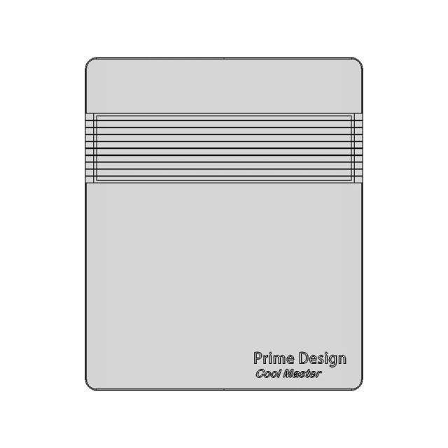
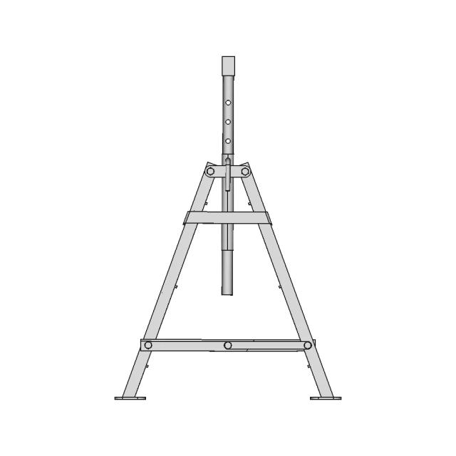
Assembly - Front View
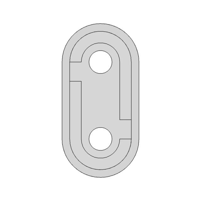
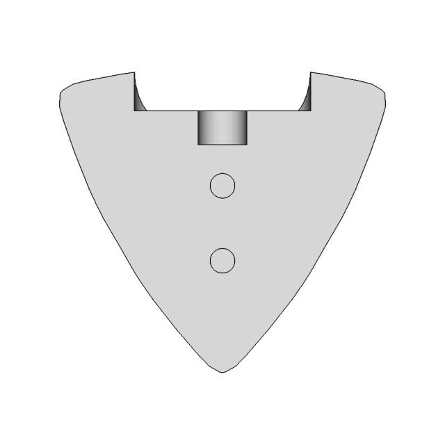
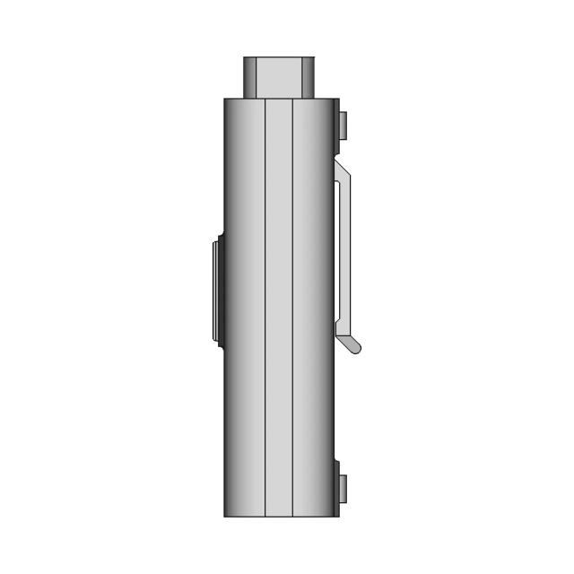
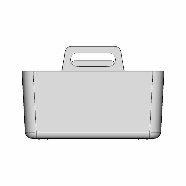
OrthographicProvides the primary view of the component's profile, clearly showing the overall length, diameter, and external features like the threaded fasteners and flange.
AI Drawing Analysis
The cards below explain how the generated drawing outputs and assets connect to the final technical sheets.
Provides the primary view of the component's profile, clearly showing the overall length, diameter, and external features like the threaded fasteners and flange.
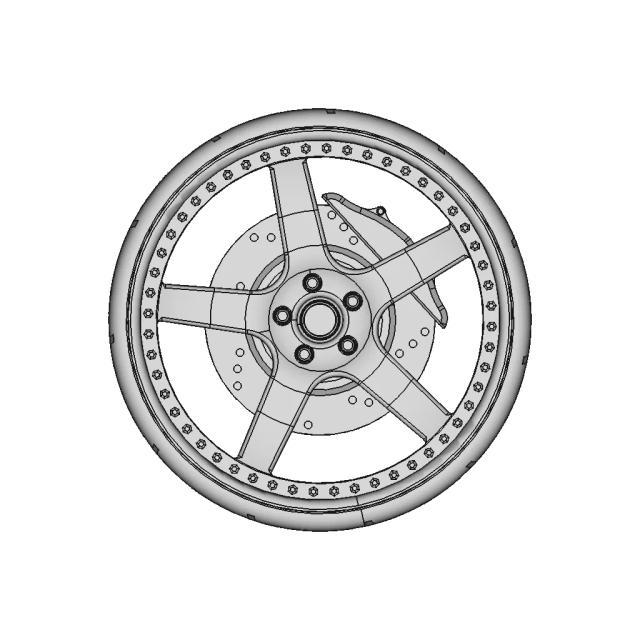
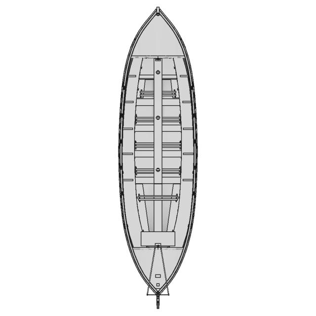
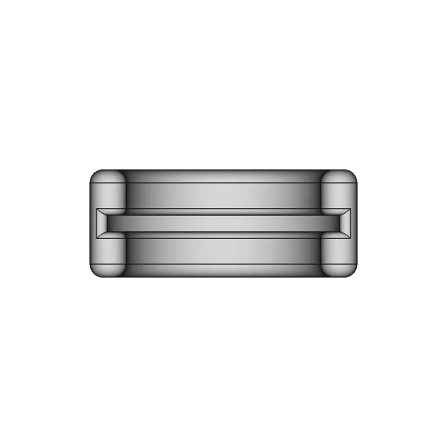
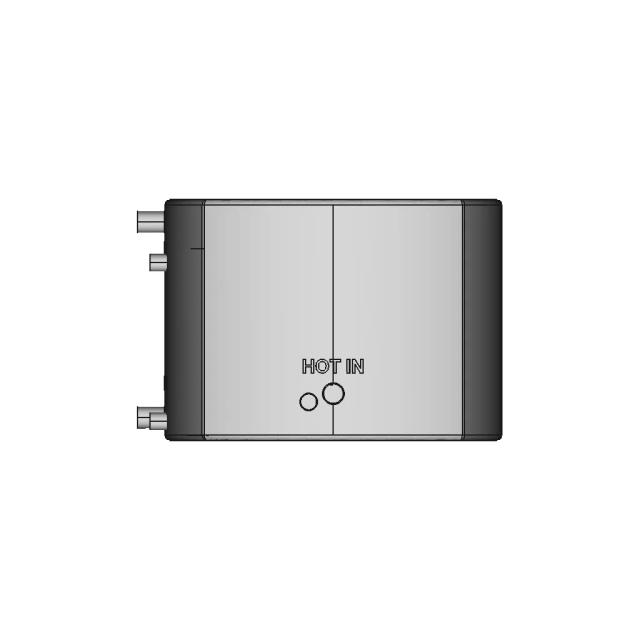
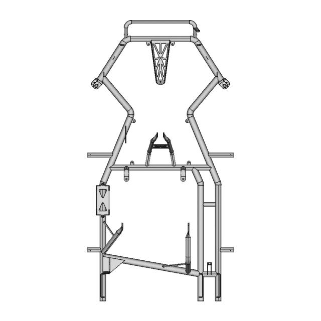
Reveals the top surface geometry, including the circular flange, the central bore, and the arrangement of the threaded fasteners, which are not visible in the Front view.
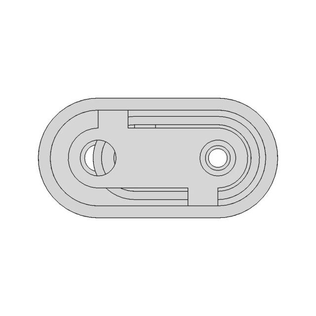
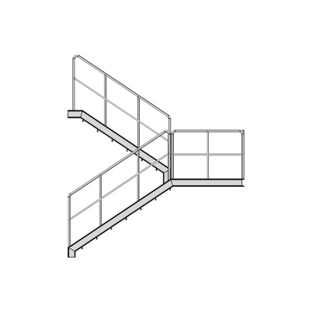
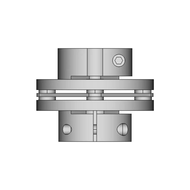
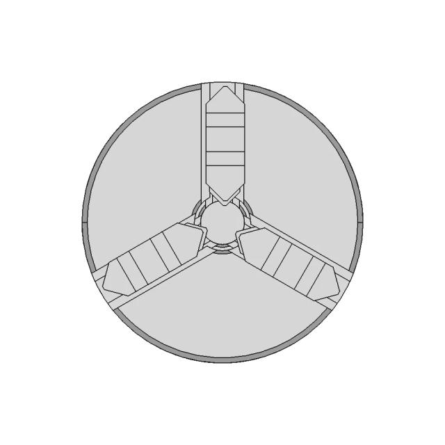
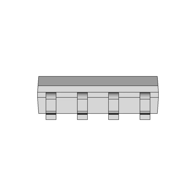
Shows the circular cross-section of the component, highlighting the internal bore and the concentric rings, which are critical for understanding the internal structure.
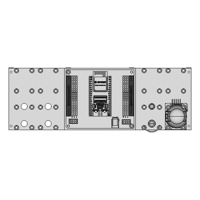
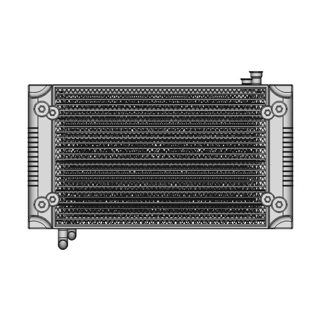
Magnifies the small threaded hole on the flange, which is critical for assembly and requires precise dimensioning.
Downloads
Each sheet available in PDF, SVG, and DXF. Click a format badge to download.
AI Transparency
These drawings were generated from the source 3D CAD geometry. The system analysed the model, selected relevant views, planned section cuts and generated drawing sheets in PDF, SVG and DXF formats.
These are 2D engineering drawings, not 3D files. Dimensions are extracted from the 3D geometry and should be verified against the source model before use in manufacturing.
Run Metadata
Explore Marathon OS
Jump to the source 3D model, generate your own drawings, or browse tools and libraries.
Open the original 3D CAD model used to generate this 2D drawing set. Review the source geometry before downloading or using the technical drawings.
Open 3D CAD model → The CAD marketplace for modern teams
Everything you need to design faster, smarter, and with more impact.

Everything you need to design faster, smarter, and with more impact.